Sense Relays on Shelves
Before the Sense Relays are fitted onto their shelves they had to be set up. The procedure and settings were available in an old BTM Maintenance Manual. Various gaps and spring pressures had to be set. Below is a spring gauge as used during W.W.II with which the set up was performed.
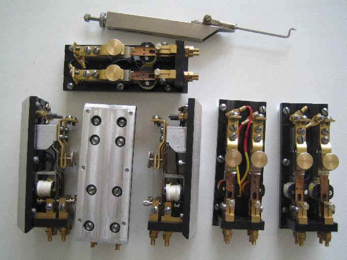
Correct setting is important for reliable operation where the armatures must respond in only a few milliseconds. Before the relays were mounted on the shelves they were first tested on a rig where an oscilloscope was used to check their performance.
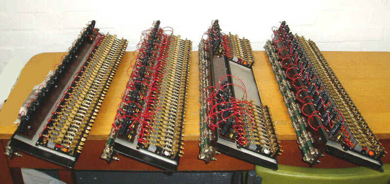
Here are four of the six shelves. Each is capable of holding 20 relays. Four are fully populated but two have 6 at each end to make up the four 26 way chains.
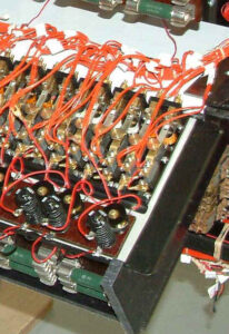
This close up shows the other items that make up the sense circuits. These are wirewound ‘clip in’ resistors, selenium rectifiers that we had made specially in the States to original specification and wire wound non-inductive resistors. These were wound by Alan Wray using insulated resistance wire on formers recovered from GPO equipment.
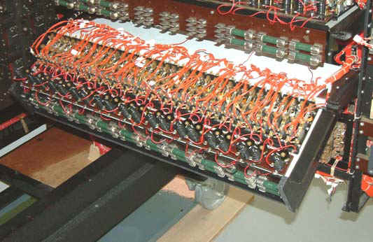
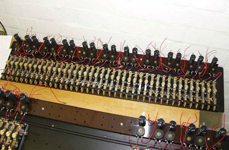
This shows 20 sense relays on a shelf. It is shown here supported on a home-made extender to enable easy of access

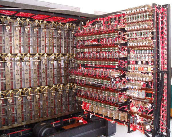
A rear view of the machine with all the sense relay shelves complete and in place and working.