The American Naval Bombe N-530
Sensing
On the N-530 the method of sensing is rather different from the BTM machine. The BTM uses high-speed Siemens relays connected in such a way that when the timing cams produce a pulse this goes through a potential divider to one side of the relay at X.
The other side is fed out to a selected input switch through the jack, then through the diagonal board and back to the other side of a relay that has diodes and resistors in the circuit. If the output of the Diagonal Board on the relay in question is at the same potential as the input pulse then the relay does not pass any current.
However, if there is no output from the diagonal board, a relay makes and this results in the STOP process. There is usually only one relay making this happen but sometimes there may be more. The state of the 26 relays in a given bank is copied to the indicator (not shown) and read on the toggles in the window (letterbox) and to where this has stopped the machine, read on the toggles in the window.
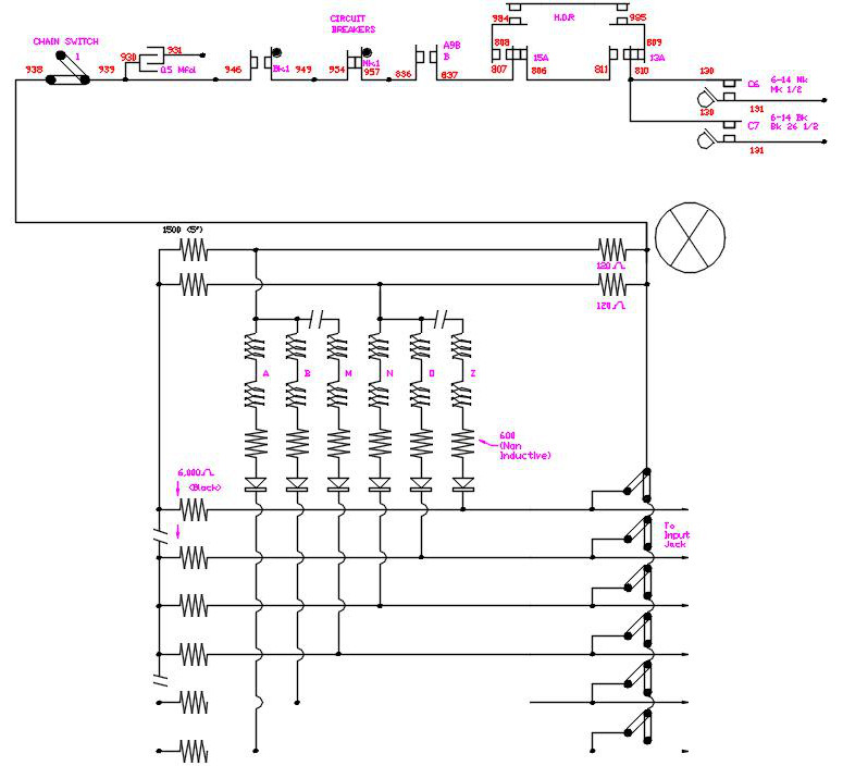
The N-530 achieves detecting state changes by a different method. Perhaps the main difference is that it looks for positives coming out of the Diagonal Board: the voltages involved are plus and minus 115v dc. In normal running the voltages are low but when there is a high from the diagonal board this is detected on one or more electronic diodes. These have four anodes; the Americans call these plates, in each glass valve, or tube; numbered 6AN6. Phil Bochicchio said that these were specially made for this project but later they were available for general use.
Cathodes are connected together in groups of five ‘this is simplified to four in the circuit above’ such that any going positive will cause current to flow in the cathode.
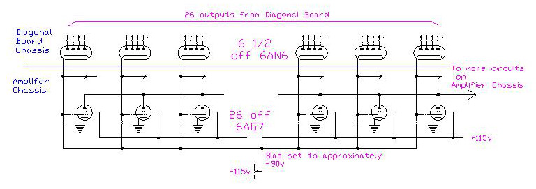
The 6AN6 valves are on the same chassis as the diagonal wiring. The outputs are connected to Amplifier chassis by a 27-way jones plug where 26 connections are used and then onto the amplifier valves
In the Amplifier Chassis, there are 26 6AG7 pentode valves, plus others that will be covered in a later chapter. These 26 have their grids connected to the cathodes of the diodes. If a diode anode detects a positive voltage, it will conduct thus raising the voltage on the grid of a 6AG7 which then conducts and lowers the voltage on the common anode connections. This, in turn, is fed to more circuits.
The N-530 achieves detecting state changes by a different method. The circuit diagram above is a simplification but covers the main elements. Perhaps the main difference is that it looks for positives coming out of the Diagonal Board: the voltages involved are plus and minus 115v dc. In normal running the voltages are low but when there is a high from the diagonal board this is detected on one or more electronic diodes. These have four anodes; the Americans call these plates, in each glass valve, or tube; numbered 6AN6. Phil Bochicchio said that these were specially made for this project but later they were available for general use.
Cathodes are connected together in groups of five ‘this is simplified to four in the circuit above’ such that any going positive will cause current to flow in the cathode.
The 6AN6 valves are on the same chassis as the diagonal wiring. The outputs are connected to Amplifier chassis by a 27- way jones plug where 26 connections are used and then onto the amplifier valves
On the Amplifier Chassis, there are 26 6AG7 valves. These have their grids connected to the cathodes of the diodes. If a diode anode ‘sees’ a positive voltage, it will conduct thus raising the voltage on the grid of a 6AG7 pentode which then conducts and lowers the voltage on the common anode connections. This, in turn, is fed to more circuits.