The American Naval Bombe N-530
Wheels (Drums) and Commutators
One point to make is that the relationship between wheels and commutators are the opposite way around to British Bombes.
The brushes are fixed to the machine whilst the commutators rotate
The brushes are at ninety degrees to the base, therefore the commutators can rotate in either direction
I was told that the carbon brushes were impregnated with silver and this was urgently recovered after WWII as the machines were being dismantled. The brush assemblies are easily removed for repair and a replacement and could be quickly and correctly timed by loosening the three fixing screws
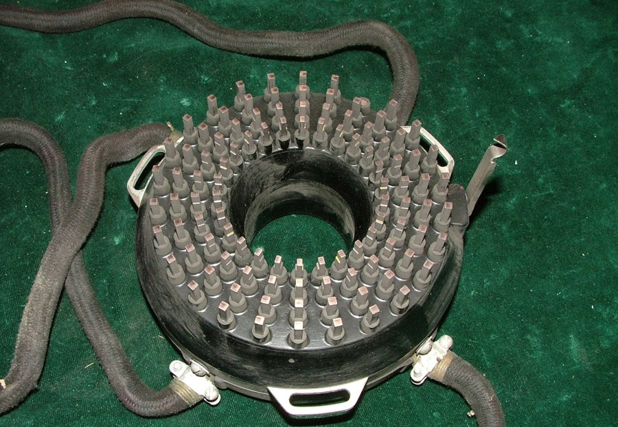
Commutators = Wheels
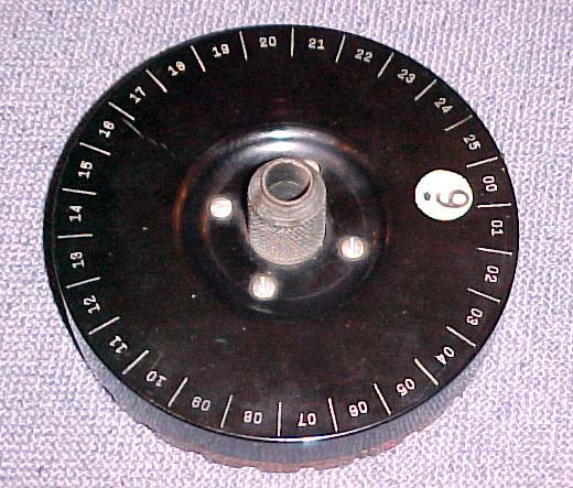
TYPICAL WHEEL
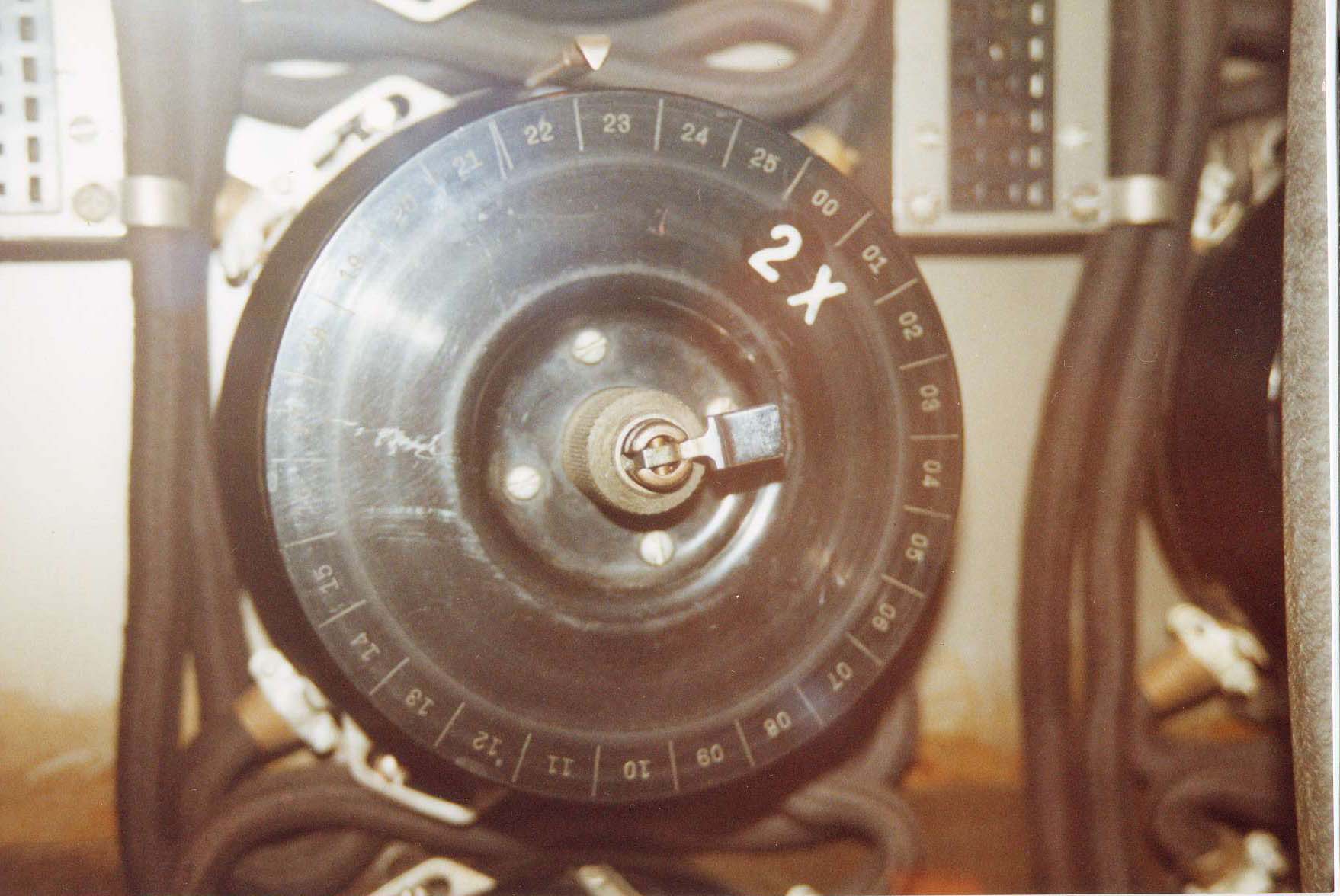
THIS SHOWS A WHEEL MOUNTED ON THE MACHINE
It is held in place by the over centre toggle. Wheels are selected in the same way as British machines but colours are not used: just the engraved digits. It has to be assumed that setting the drums has to have some form of a 26-way detent system. Letters such as ZZA are not used. The menu defines the setting by what is called a displacement, as a numeric. The number of wheels must have been huge.
Five basic, two for German surface fleet and two ‘Greek’ wheels. Sixteen Letchworth Enigmas and 120 or so machines. Around 13.500 in total!
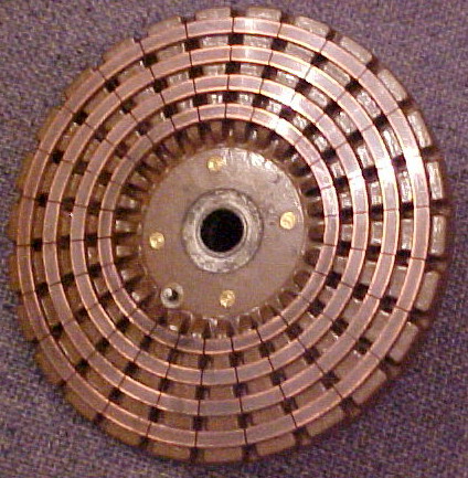

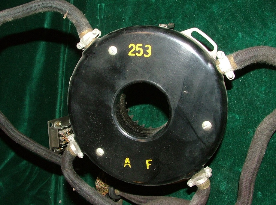
This shows the internal wiring of a wheel. In this case, it is a test wheel with one segment isolated from the rest. Between the two red marks
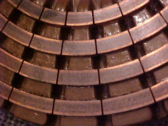
This example shows all segments separated on all four rings. When this model is used on timing wheels some of the segments are semi-continuous.
There is no need for heavy current circuit breaker because the brush tips straddle commutator segments. More often than not there will be no voltage difference between adjacent segments
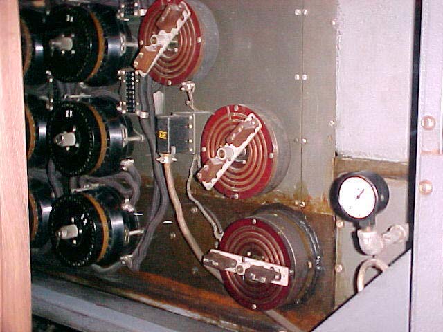
When commutators are used as timing wheels they are mounted on the machine the opposite way around. The commutators then face outwards. An arm is attached to a shaft which does not have any ratchet or detent mechanism. To these arms are attached brush holders where the brushes are connected in pairs and make the appropriate connection between the selected rings.
Note on the right-hand side of the image above, the oil pressure gauge: part of the lubrication