The American Naval Bombe N-530
Power
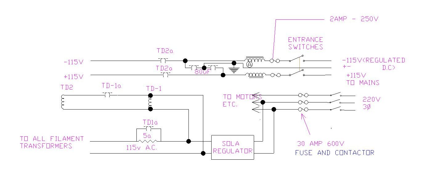
Above, the main power circuit diagram
The power input is 220V three-phase, the standard American voltage at 60 Hz
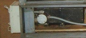
This first goes to a fuse and contactor unit mounted on the lower left end of the machine. The SOLA regulator can also be seen; the very large black unit.
A relay (50a) then energises another contactor that connects three-phase power to the motor. At the same time, two phases are connected to the SOLA Regulator, This is a constant voltage transformer where a large swing of input voltage results in a very small change in output. CVT is rarely seen, even in the 1940s. A full description is added at the end of this record.
The company SOLA, is still in existence but is now called SOLAHD. They still make constant voltage transformers that are very similar to the 1943 versions
This output of the SOLA regulator is fed to all the filament (heater) transformers on four chassis.
The output at 115V AC is also rectified to produce +115v and -115v. This rectification is not shown on any document but the smoothing is shown in the circuit diagram above, with chokes and capacitors.
115v ac is then routed to the Regulator Chassis where it is fed through a very heavy 5ohm 160W resistor. This results in limiting the heater current to the output of transformers whilst the heater is warming up.
Applying power to the time delay relay TD-1 starts it running for 45 seconds, then contacts bypass the large resistor applying full power to all the heater.
Also when TD-1 reaches its final state, TD-2 starts to run and when this has run for a further 45 seconds +115 v and -155 v are both made available to the rest of the machine.
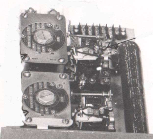
The above shows the time delay relays fitted to the Regulator Chassis.
The two relays, WARD LEONARD #362 – 666 relays are shown on the left
The 160W resistor and the power to the indicator lamp series resistors on the right
Ward Lenard time delay relays are still being made but maybe not this model. They work by a small motor driving a cam that makes or breaks the heavy-duty contacts carrying 115 ac
A further DC voltage is needed to supply the relays. This is taken from the 115vac input and rectified single phase using a Selenium rectifier and a 125 mfd smoothing electrolytic capacitor
Constant Voltage Transformer (CVT) how does it work?
AC stabilisation can be achieved using a simple magnetic device which has no moving parts.
This is a process of producing a constant ac voltage from a varying ac voltage supply and involves the use of saturable reactors. The latter may be incorporated in a special transformer magnetic saturation being produced in a part of the magnetic circuit.
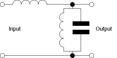
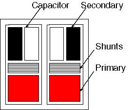
The winding arrangement and construction of one such constant voltage transformer are shown in the diagram below:
The core is a three-limbed shell with a magnetic leakage path dividing the winding space. On the upper winding space is the primary and a compensating winding while the lower winding space carries the secondary which has a capacitor connected across it. An increasing voltage applied to the primary produces an increasing flux in the main magnetic circuit and the secondary voltage increases proportionally to this voltage. The increasing flux produces an increase in the leakage reactance of the secondary and this approaches a value which resonates with the capacitor connected across it. As the condition of resonance is reached the secondary current rises rapidly saturating the lower portions of the magnetic circuit. The flux due to the primary is diverted through the magnetic shunt and further increases in primary voltage produce little change in the secondary emf. It increases very slowly and this is offset by the emf induced in the compensating winding on the upper portion of the core which is connected in series opposition to the secondary winding.
Thus once the secondary is brought to resonance the output voltage from the secondary and compensating windings is constant and it is under these conditions that the transformer is used.
The advantage of this form of stabilisation is that it can be applied to the heater supplies in addition to any HT supplies derived from it. Owing to the non-sinusoidal waveform however readings taken with the usual rectifier-type meters are subject to error.
The compensating winding produces a small voltage which is used to ‘buck’ the output voltage.
To produce a sinusoidal waveform a further winding is added which is coupled via a magnetic gap. This extra ‘neutralising’ winding can be arranged to provide a suitable amount of 3rd and 5th harmonics which when summed with the output ‘square’ wave above results in a sinewave.